


I’m experimenting with several accelerometer/gyroscope sensors for different purposes, from robotics, drone equilibrium, vibration control, building oscilations, to seismicity.
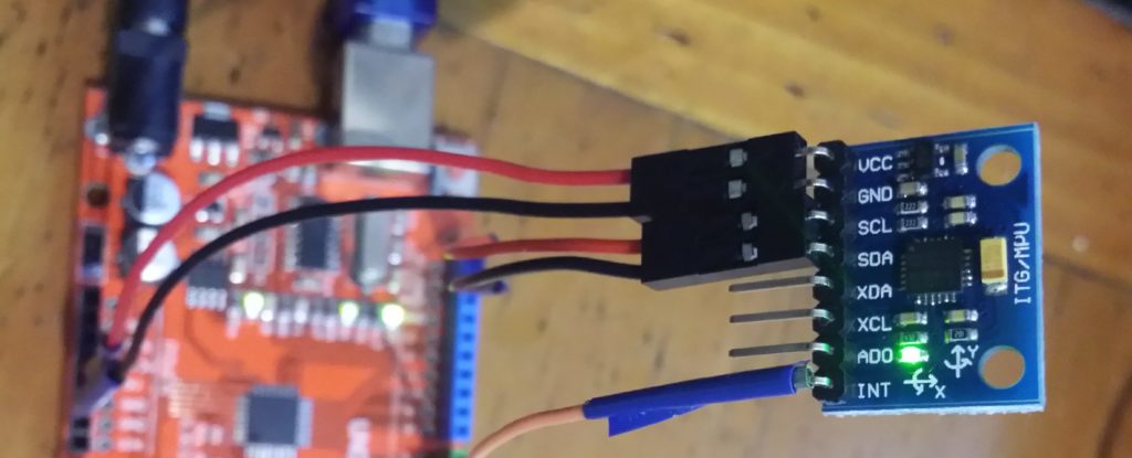
In this case we are using the the MPU-6050 6-axis accelerometer/gyroscope.
Some of its features are I2C Digital-output of 6 or 9-axis MotionFusion data in rotation matrix, quaternion, Euler Angle, or raw data format. This may be very convenient depending on the use and algebraic model of the data being processed. For example some drone software may either prefer matrix or quaternion representation to feed its internal coordinates engine. Input Voltage: 5V. Tri-Axis angular rate sensor (gyro) with a sensitivity up to 131 LSBs/dps and a full-scale range of ±250, ±500, ±1000, and ±2000dps. Tri-Axis accelerometer with a programmable full scale range of ±2g, ±4g, ±8g and ±16g. Digital Motion Processing™ (DMP™) engine offloads complex MotionFusion, sensor timing synchronization and gesture detection.
There are several implementations of sensor modules with different features and caveats. See here.
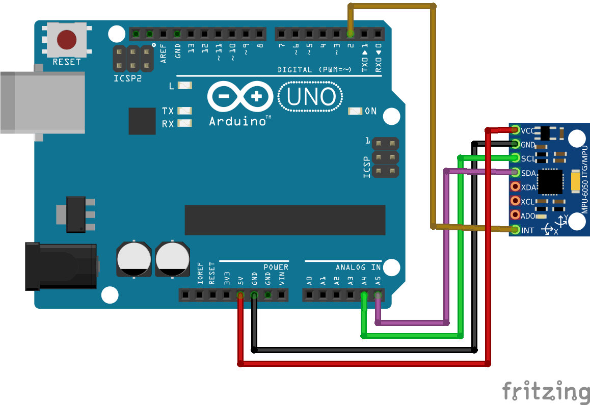
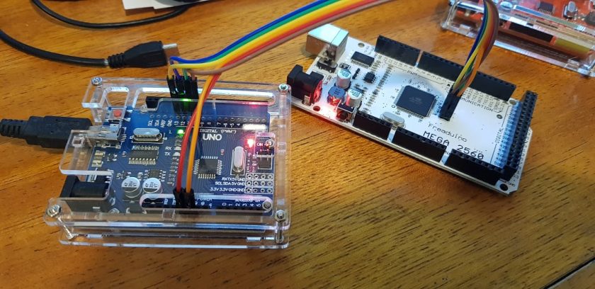
Connect your sensor board with Arduino UNO as shown. This is actually an I2C connection. This assumes that your board has I2C hardware.
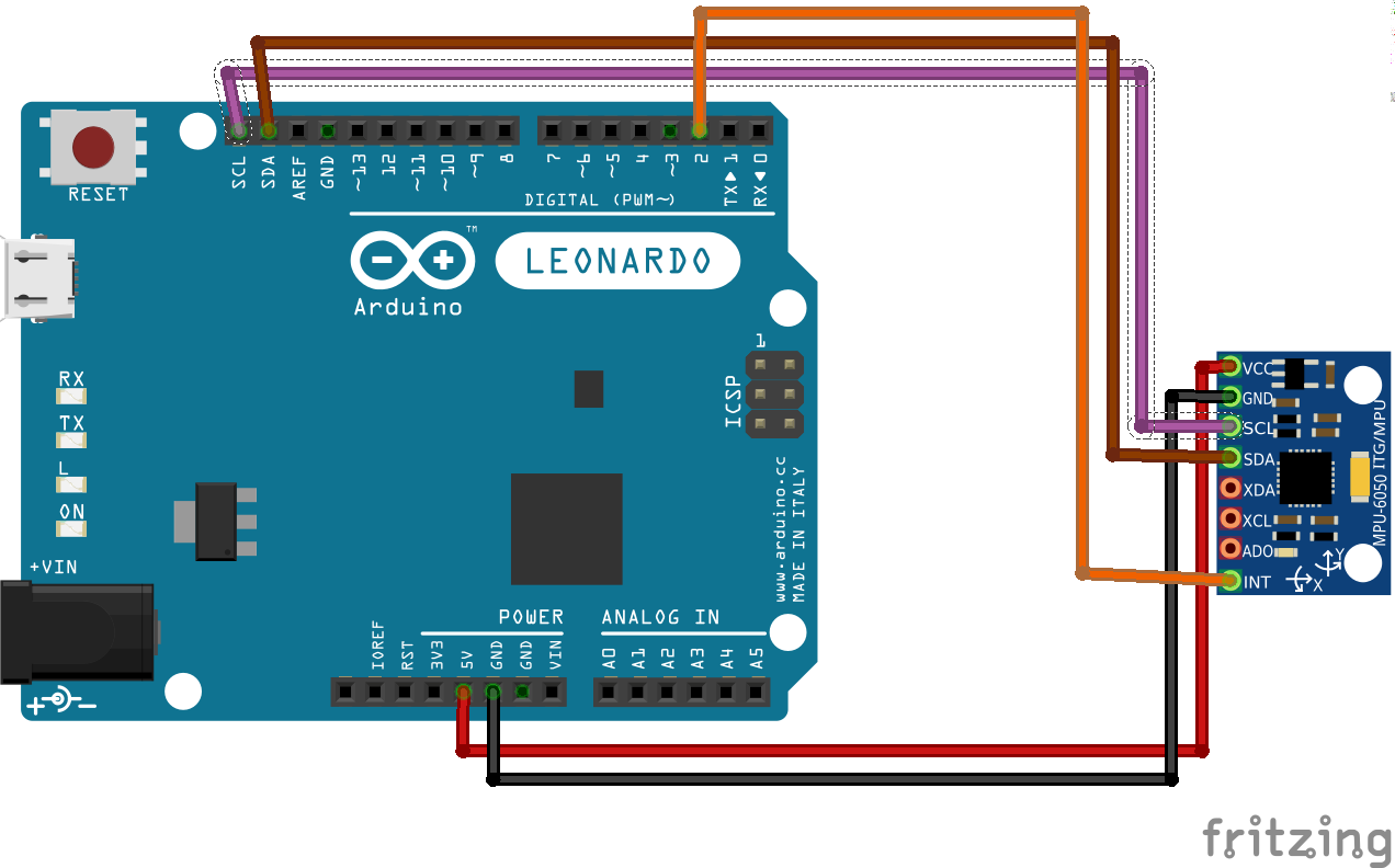
For software I2C connection see some other examples.
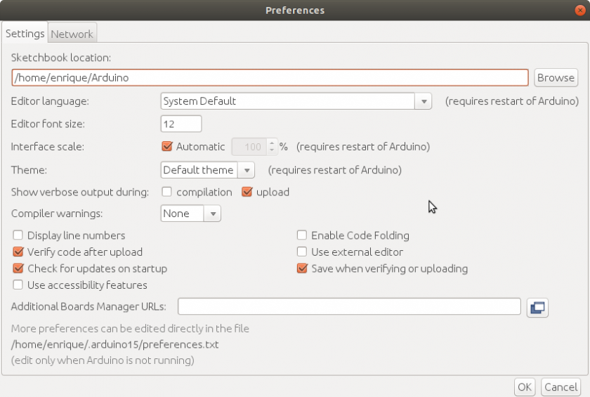
Load the following code to your Arduino IDE:
// MPU-6050 Short Example Sketch
 // By Arduino User JohnChi
 // August 17, 2014
 // Public Domain
 #include
 const int MPU_addr=0x68; // I2C address of the MPU-6050
 int16_t AcX,AcY,AcZ,Tmp,GyX,GyY,GyZ;
 void setup(){
 Wire.begin();
 Wire.beginTransmission(MPU_addr);
 Wire.write(0x6B); // PWR_MGMT_1 register
 Wire.write(0); // set to zero (wakes up the MPU-6050)
 Wire.endTransmission(true);
 Serial.begin(9600);
 Serial.println("Starting MPU6050 Enrique Latorres");
 }
 void loop(){
 Wire.beginTransmission(MPU_addr);
 Wire.write(0x3B); // starting with register 0x3B (ACCEL_XOUT_H)
 Wire.endTransmission(false);
 Wire.requestFrom(MPU_addr,14,true); // request a total of 14 registers
 AcX=Wire.read()<<8|Wire.read(); // 0x3B (ACCEL_XOUT_H) & 0x3C (ACCEL_XOUT_L)
 AcY=Wire.read()<<8|Wire.read(); // 0x3D (ACCEL_YOUT_H) & 0x3E (ACCEL_YOUT_L)
 AcZ=Wire.read()<<8|Wire.read(); // 0x3F (ACCEL_ZOUT_H) & 0x40 (ACCEL_ZOUT_L)
 Tmp=Wire.read()<<8|Wire.read(); // 0x41 (TEMP_OUT_H) & 0x42 (TEMP_OUT_L)
 GyX=Wire.read()<<8|Wire.read(); // 0x43 (GYRO_XOUT_H) & 0x44 (GYRO_XOUT_L)
 GyY=Wire.read()<<8|Wire.read(); // 0x45 (GYRO_YOUT_H) & 0x46 (GYRO_YOUT_L)
 GyZ=Wire.read()<<8|Wire.read(); // 0x47 (GYRO_ZOUT_H) & 0x48 (GYRO_ZOUT_L)
 Serial.print("AcX = "); Serial.print(AcX);
 Serial.print(" | AcY = "); Serial.print(AcY);
 Serial.print(" | AcZ = "); Serial.print(AcZ);
 Serial.print(" | Tmp = "); Serial.print(Tmp/340.00+36.53); //equation for temperature in degrees C from datasheet
 Serial.print(" | GyX = "); Serial.print(GyX);
 Serial.print(" | GyY = "); Serial.print(GyY);
 Serial.print(" | GyZ = "); Serial.println(GyZ);
 delay(333);
 }
Compile and load to your Arduino board. Open the serial Monitor to see the results.
Starting MPU6050 Enrique Latorres
 AcX = 13344 | AcY = -1156 | AcZ = 9028 | Tmp = 20.06 | GyX = -64 | GyY = 20 | GyZ = -9
 AcX = 13336 | AcY = -1116 | AcZ = 9284 | Tmp = 20.06 | GyX = -65 | GyY = 43 | GyZ = -44
 AcX = 13476 | AcY = -1048 | AcZ = 9144 | Tmp = 19.97 | GyX = -93 | GyY = 43 | GyZ = -32
 AcX = 13276 | AcY = -1164 | AcZ = 9160 | Tmp = 20.11 | GyX = -77 | GyY = 31 | GyZ = -36
 AcX = 13268 | AcY = -1136 | AcZ = 9208 | Tmp = 20.06 | GyX = -76 | GyY = 51 | GyZ = -65
 AcX = 13408 | AcY = -1016 | AcZ = 9212 | Tmp = 20.06 | GyX = -85 | GyY = 34 | GyZ = -51
 AcX = 13484 | AcY = -1172 | AcZ = 9136 | Tmp = 20.11 | GyX = -18 | GyY = 30 | GyZ = -26
 AcX = 13420 | AcY = -1144 | AcZ = 9124 | Tmp = 20.11 | GyX = -79 | GyY = 74 | GyZ = -37
After a simple shaking we see that it is working in 2g range and 32767 is top of scale. For all six axis the working range is -32768, +32767. That is 16384 is 1g. So what AcX, AcY and AcZ are reading is the orthogonal projection of earth gravity to each of the axis. If you place the sensor in an horizontal stand it will get something near 16384 plus minus some noise.
Also computing something like √((13344 ÷ 16384) ² + (- 1156 ÷ 16384) ² + (9028 ÷ 16384) ² )= 0.9858707387 ~ = 1,0 g = 9.80665 m/s2 Notice gravity may vary according different factors and places on Earth. Also this equipment reads raw data without calibration.
Another example using Rowberg's Library.
// I2C device class (I2Cdev) demonstration Arduino sketch for MPU6050 class
 // mofdified from example by Jeff Rowberg
 #include "I2Cdev.h"
 #include "MPU6050.h"
 #include "Wire.h"
 MPU6050 accelgyro(0X68); //default address I2C is 0x68
 //declare variables
 int16_t ax, ay, az;
 int16_t gx, gy, gz;
 int16_t temp;
 float temp_MPU;
 #define LED_PIN 13
 bool blinkState = false;
 void setup() {
 Wire.begin();
 Serial.begin(38400);
 Serial.println("Initializing I2C devices...");
 accelgyro.initialize();
 Serial.println("Testing device connections...");
 Serial.println(accelgyro.testConnection() ? "MPU6050 connection successful" : "MPU6050 connection failed");
 // change accel/gyro offset values to zero
 accelgyro.setXGyroOffset(0);
 accelgyro.setYGyroOffset(0);
 accelgyro.setZGyroOffset(0);
 // configure Arduino LED for
 pinMode(LED_PIN, OUTPUT);
 Serial.println("MPU-6050 example - Enrique Latorres");
 Serial.print("ax"); Serial.print("t");
 Serial.print("ay"); Serial.print("t");
 Serial.print("az"); Serial.print("t");
 Serial.print("temp"); Serial.print("t");
 Serial.print("gx"); Serial.print("t");
 Serial.print("gy"); Serial.print("t");
 Serial.println("gz");
 }
void loop() {
// read raw accel/gyro measurements from device
//accelgyro.getMotion6(&ax, &ay, &az, &gx, &gy, &gz);
accelgyro.getAcceleration(&ax, &ay, &az);
accelgyro.getRotation(&gx, &gy, &gz);
temp=accelgyro.getTemperature();
// display tab-separated accel/gyro x/y/z values
Serial.print(ax); Serial.print("t");
Serial.print(ay); Serial.print("t");
Serial.print(az); Serial.print("t");
//convert integer to temperature in centigrades Celsius
//https://www.i2cdevlib.com/forums/topic/53-mpu-6050-temperature-compensation/
temp_MPU=float(temp)/340+36.53;
Serial.print(temp_MPU); Serial.print("t");
Serial.print(gx); Serial.print("t");
Serial.print(gy); Serial.print("t");
Serial.println(gz);
// blink LED to indicate activity
blinkState = !blinkState;
delay(300); //just slow down a little bit
digitalWrite(LED_PIN, blinkState);
}
Compiling and Loading the program gets the following result on Serial Monitor.
MPU-6050 example - Enrique Latorres
 ax ay az temp gx gy gz
 12016 -2038 10648 20.95 61 -21 46
 12030 -1838 10594 20.96 -102 -23 -115
 12046 -1712 10550 20.95 -102 23 -97
 11990 -1978 10640 20.93 32 62 85
 12040 -1848 10616 20.97 -114 15 -105
 11972 -1852 10642 20.94 -27 11 -5
 11942 -1810 10688 20.94 -86 75 -13
 11956 -5784 12308 20.96 -3029 822 -3583

Wow, gracias por toda la información que plasmaste en el blogJulio
Hola, tengo que realizar un proyecto en donde utilizo de 4 a 5 módulos GY-521. Tengo dudas de si puedo conectarlos en serie (agrupar los datos de salida) o cada módulo tiene que tener conexión independiente.
la alimentacion oprque va a 5v si el sensor dices que va a 3v? Gracias!
Está equivocado. Creo que copié las especificaciones del de 3v pero este es de 5V. Ya lo corrijo.
Los módulos se conectan por i2c. Se les tiene que programar diferentes direcciones. Entonces se ponen en paralelo.
Hola, dónde están declarados los pines de entrada? necesito cambiarlos porque estoy usando un sensor de presión SFE_BMP180 en conjunto y ambos usan los análogos 4 y 5 como entrada, no encuentro la parte del código donde los especifica. Gracias
Hola Mackarena. Supongo que haces referencia al uso de los pines de e/s 4 y 5 del esquema al final. Lo que sucede es que el ejemplo (con el programa) lo hice solamente con los pines dedicados para I²C. El que aparece arriba. Y para ver un ejemplo con los pines definidos por software dejo allí un link que lleva a un artículo de un tercero que hace ese ejemplo.