


When trying to connect an LCD Display to your Arduino project, a clever solution is to use an I2C-LCD adapter. In this case the FC-113 IIC/I2C serial interface adapter module for 1602 or 2004 LCD Display. This will decrease the number of pins used in your Arduino board, leaving place for other sensors and actuators.
The connection between the LCD Display and the I2C Module is quite straight forward. simply connect pin n of LCD to pin n (1 to 1, 2 to 2, and so on) of Serial Module for all 16 pins, as shown on the photograph. If it doesn’t have numbers on pins, usually pin 1 is marked somehow different (a filler marker, a square instead of circle, etc), so you know the order. I suggest that you solder a female header single row 16 pin on the LCD PCB so you can plug the serial controller pin header to it. If the serial controller doesn’t have a male pin header, then solder one to the serial controller. If you are going to experiment, try not to solder components directly. Soldering and unsoldering causes heating to PCB (Printed Circuit Board) and components, and causes damage and malfunction to them. Plug the controller to the LCD display like this:
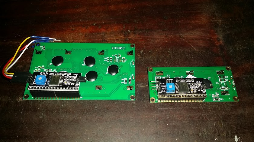
Notice that it will work fine either with 1602 (16 charcter by 2 lines) or with 2004 (20 characters by 4 lines) LCD boards. It also has 4 pins to connect to your Arduino board. These are +Vcc, -Gnd, SDA and SLC. You may find it easier if you get a 4 pin female header connector for cable and solder your cables there. You may use this cables for other projects later if you want.
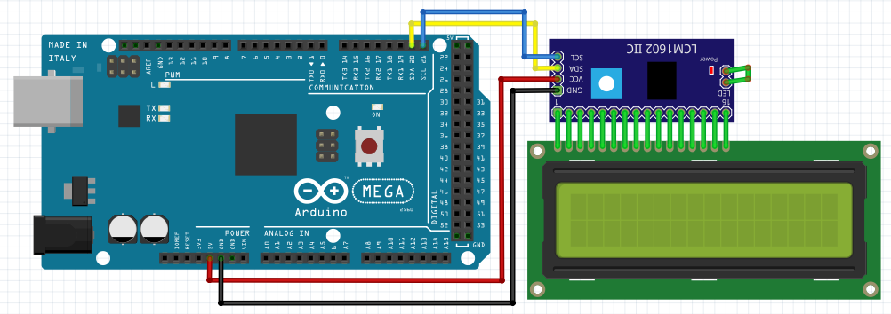
The connection is like this. +Vcc connects to any +5v female header pin at your Arduino board, -Gnd to a GND header, SDA and SLC to their respective header at your Arduino board. Notice that some boards may not have SDA and SLC marked. In this case you have to check which pin headers of your board are used for I2C communication. On Arduino UNO usually A5 is SLC and A4 is SDA. On arduino UNO Rev.3 pin 16 is SDA and pin 17 is SCL. Some versions of board may be marked, some not. In Arduino Mega 2560, SDA is 20 and SLC is 21.
I2C or IIC or I2C communication is a model of component interconnect. It allows up to 128 components to share a simple serial bus of 2 lines (SDA data and SLC clock). You have to check the data specs of the component you are connecting, because both lines need a pull-up resistor (resistor connected to +Vcc) in order to get a high level in case all components are “disconnected” from the bus. In this case the pull-ups are included in the PCBs. See: https://en.wikipedia.org/wiki/I%C2%B2C
The serial controller has a jumper, that allows to turn off backlight if removed. Also you can turn off the backlight through software, but you will not be able to turn it on if this jumper is removed. There is also a led, close to it, that shows whether the board has energy.
There is a potentiometer were you can adjust the contrast of your LCD. Try rotating it while on until characters are clear on the screen.
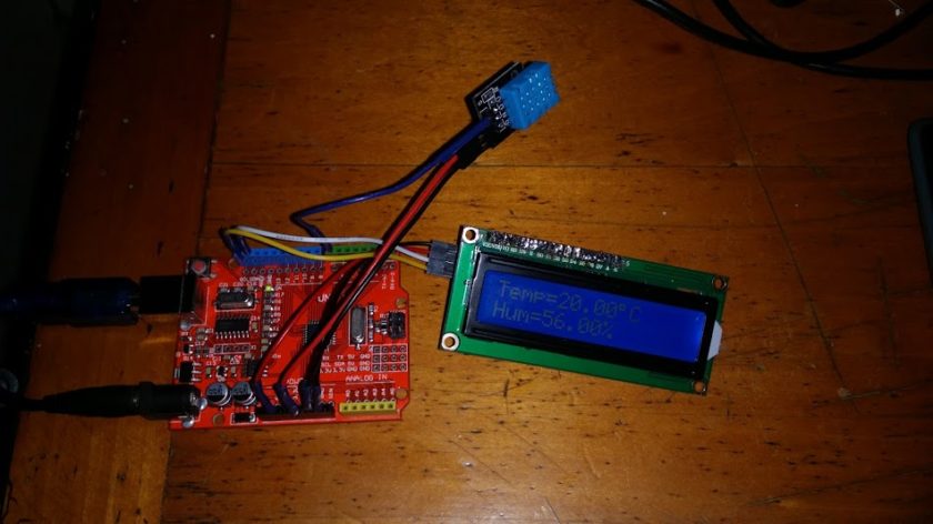
Just connect your LCD and Serial controller like this:
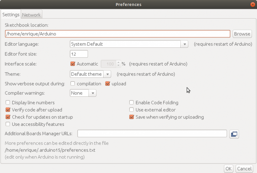
You need the I2C LCD Library. You can Download Malpartida’s library from his site. https://bitbucket.org/fmalpartida/new-liquidcrystal/downloads and Download the newest stable version. NewliquidCrystal_1.3.4.zip in this case. Just unzip it in a new folder inside your library directory. Now you can use this library on your Arduino IDE environment.
The serial controller also has three contacts on the PCB, usually named A0, A1 and A2. This are the less significative bits of the I2C address of the serial controller. If you short these connections the address of the component will change these bits to zero. They are one by default. My component has address 0x3F. So it could be changed to 0x38 through 0x3F. But yours may have a different address. In this case you should run a address scanner for I2C. Create a new sketch and name it something like “i2c_scanner” and save, with the following code:
//Written by Nick Gammon
 // Date: 20th April 2011
 //http://www.instructables.com/id/I2C-LCD-Controller-the-easy-way/
 #include
 void setup() {
 Serial.begin (9600);
 // Leonardo: wait for serial port to connect
 while (!Serial)
 {
 }
Serial.println ();
Serial.println (“I2C scanner. Scanning …”);
byte count = 0;
Wire.begin();
for (byte i = 1; i < 120; i++)
{
Wire.beginTransmission (i);
if (Wire.endTransmission () == 0)
{
Serial.print (“Found address: “);
Serial.print (i, DEC);
Serial.print (” (0x”);
Serial.print (i, HEX);
Serial.println (“)”);
count++;
delay (1); // maybe unneeded?
} // end of good response
} // end of for loop
Serial.println (“Done.”);
Serial.print (“Found “);
Serial.print (count, DEC);
Serial.println (” device(s).”);
} // end of setupvoid loop() {}
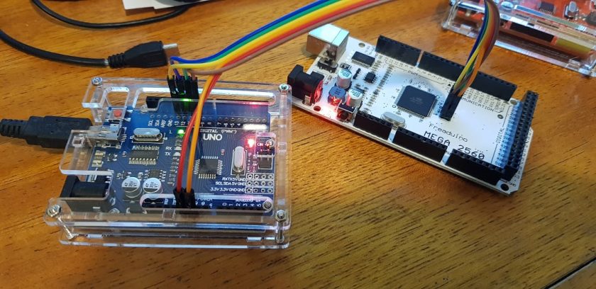
Run this program on your Arduino and it will tell you the address of your LCD-I2C component. It answers through the USB-Serial interface so you have to activate the IDE’s Serial Monitor to see it.
I2C scanner. Scanning ...
 Found address: 63 (0x3F) //address found may vary
 Done.
 Found 1 device(s). //I assume you only have this device connected
After this you can run a simple Demo for your LCD Display.
/*
* I2C/IIC LCD Serial Adapter Module Demo
*/
#include
#include
#include
// 0x3F is the I2C bus address for my unmodified module
// if you get another address from the i2c scanner put that
#define I2C_ADDR 0x3F//Pin description for 2004A and 1602A LCD
LiquidCrystal_I2C lcd(I2C_ADDR,2,1,0,4,5,6,7);// Pin 13 has an LED connected on most Arduino boards.
// give it a name:
int led = 13;void setup()
{
// You must initialize the library with the size of the Display before using it
//Choose/uncomment the size of your display
// lcd.begin(20, 4);//20 columns 4 rows for 2004A
lcd.begin(16, 2);//16 columns 2 rows for 1602Alcd.setBacklightPin(3,POSITIVE);
//lcd.setBacklight(HIGH); // NOTE: You can turn the backlight off by setting it to LOW instead of HIGH
lcd.setBacklight(LOW);
lcd.clear(); // clean screen and sets cursor to (0,0)
// initialize the digital pin as an output.
// will not blink without it
pinMode(led, OUTPUT);
}void loop()
{
lcd.setCursor(0,0);
lcd.print(“Enrique Latorres”);
lcd.setCursor(0,1);
lcd.print(“I2C Module Demo”);
//uncomment if using 2004A
// lcd.setCursor(0,2);
// lcd.print(“third line 123456”);
// lcd.setCursor(0,3);
// lcd.print(“fourth line ASDF”);digitalWrite(led, HIGH); // turn the LED on (HIGH is the voltage level)
lcd.setBacklight(LOW); //turn off backlight
delay(1000); // wait for a second
digitalWrite(led, LOW); // turn the LED off by making the voltage LOW
lcd.setBacklight(HIGH); //turn on backlight
delay(1000); // wait for another second
}
Now you should have a blinking display with your message on it. Also the pin 13 led will blink with opposite value than the backlight.
Greetings.
No se que estaba haciendo mal, intenté de todo con muchas librerias incluso la de malpartida pero solo con tu ejemplo funcionó.
así que gracias por la ayuda 😀
Me alegro. Saludos
Thankyou very much!
It’s work for me 😉