


I’m interested in measuring these parameters (Humidity, Barometric Pressure and Temperature) to collect information using many low costs sensors along the Geophysical Network for several purposes.
So I’m experimenting with several low cost sensors to see how they do and whether they are suitable for the task.
In this case we are testing the BME280 integrated environmental sensor, in a module similar to this one. It was developed specifically for mobile applications where size and low power consumption are key design constraints. See here. It is a Temperature Humidity Pressure Sensor, I2C and SPI capable. So it can be connected through any of both protocols.
In this example we use an Arduino UNO R3 compatible Red and a GY-BME280-5v High Precision Barometric Pressure Module board. Notice that there are plenty of providers of BME280 modules and Arduino compatible boards, and the order of the pins may vary from one to another. So do check where are those pins in your board. Besides this module is for 5v power and interface. There are modules for 3.3v, so you may need voltage splitter for inputs and outputs, pull-ups and/or separate power source.
We use cactus.io BME280 SPI library. Many other Libraries will work also. But you’ll have to change the library include and also some libraries may have different names in the BME object creation an in its methods. Also the creation of the BME_SPI object depends whether the board has SPI hardware. In this case we do not. So we start an BME_SPI software connection. It will use the specified pins to communicate with the module. Notice that this library has option to add calibration parameters. The line “bme.setTempCal(-2);” will subtract two degrees to any reading in any temperature scale.
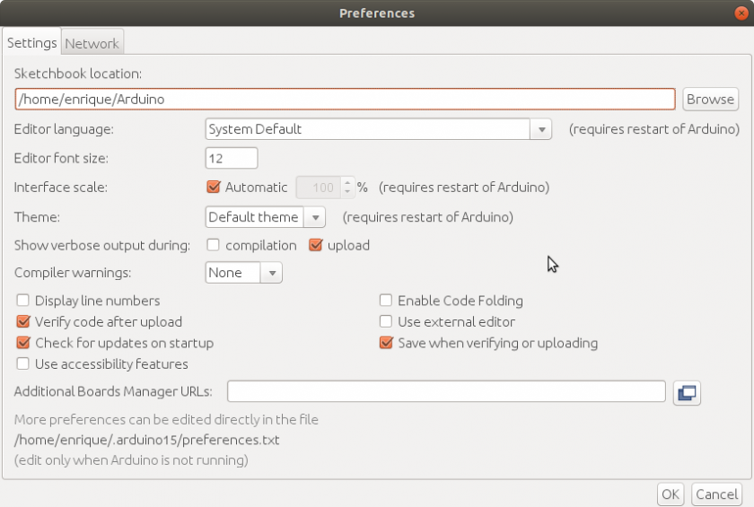
If you have problems compiling the SPI library included in Arduino IDE, you may have to update your Arduino IDE version. Download the new version and install with the install.sh script.
Your BME280 module has at least the following pins:
VCC/VIN //5Volt input
GND // Ground connection
SCK/SCL // Serial Clock
MISO/SDA/SDI // Serial Data Out
MOSI/SDO // Serial Data In
CS/CSB // Chip Select
It may have an 3VO output that can be used to power some low power 3v device. Pin names may vary according to model.
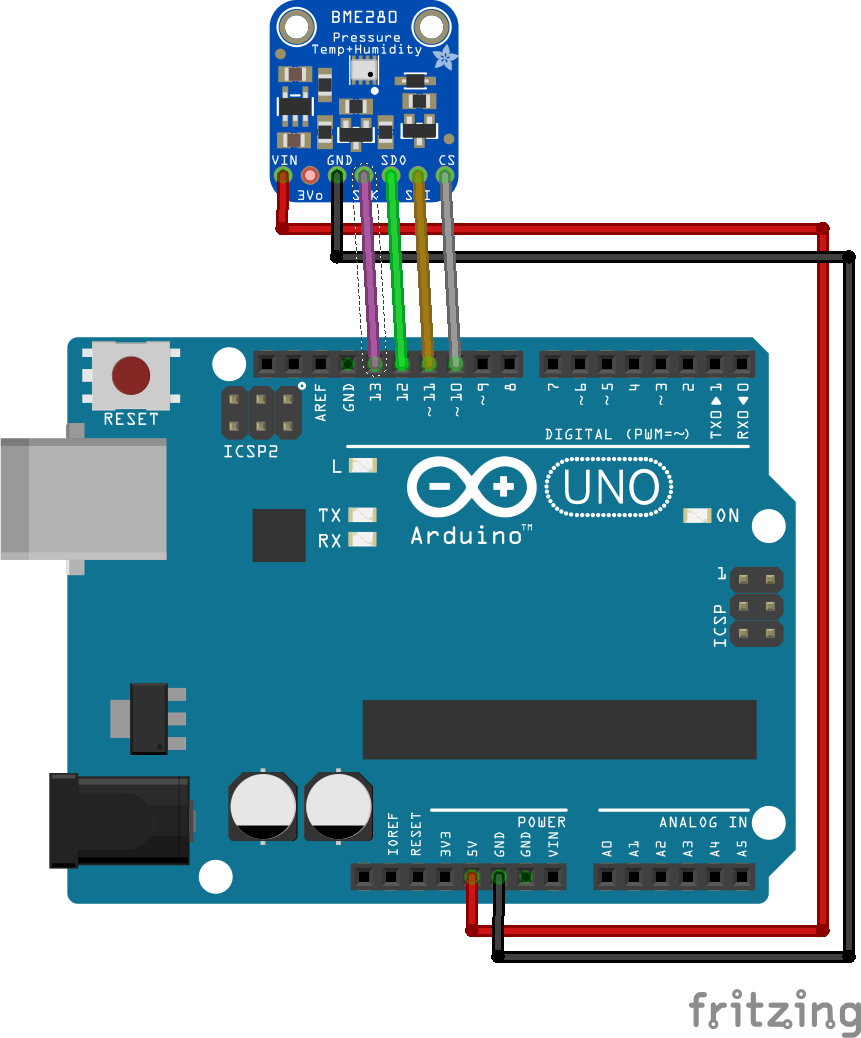
For the SPI protocol (software connection) we must connect SCK/SCL to pin 13 of Arduino UNO, MOSI/SDO to pin 12 , MISO/SDA/SDI to pin 11 and CS/CSB to pin 10. If you have more than one module they are connected in parallel on SCK, MISO and MOSI but connect the other CS to another output pin.
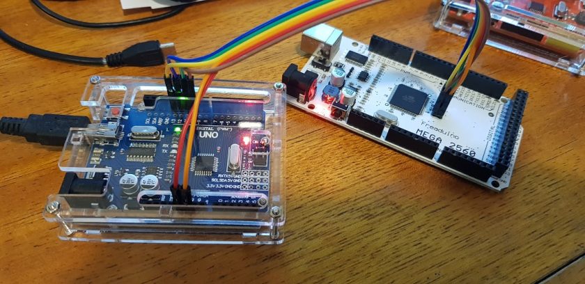
Connect Arduino UNO and BME280 module as shown.

Open Arduino IDE and paste the following code:
/***************************************************************************
 BME280 humidity, temperature & pressure sensor test program with SPI bus
 ***************************************************************************/
#include “cactus_io_BME280_SPI.h”
#include “SPI.h”// Communications pins order. Depends on your module
// Vcc Gnd Scl/Sck-13Sdo/Miso-12 Sdak/Mosi-11 Csb/Cs-10
#define BME_SCK 13 // Serial Clock
#define BME_MISO 12 // Serial Data Out
#define BME_MOSI 11 // Serial Data In
#define BME_CS 10 // Chip Select// Create the BME280 object with the right pins
BME280_SPI bme(BME_CS,BME_MOSI,BME_MISO,BME_SCK);void setup() {
Serial.begin(115200);
Serial.println(“Bosch BME280 Barometric Pressure – Humidity – Temp Sensor”);
if (!bme.begin()) {
Serial.println(“Could not find a valid BME280 sensor, check wiring!”);
while (1);
}
bme.setTempCal(-1);
Serial.println(“PressuretHumditytTemp”);
}void loop() {
bme.readSensor();
//Serial.print(bme.getPressure_MB()); Serial.print(“tt”); // Pressure in millibars
Serial.print(bme.getPressure_HP()); Serial.print(“tt”); // Pressure in hectapascals
Serial.print(bme.getHumidity()); Serial.print(“tt”);
Serial.print(bme.getTemperature_C()); Serial.println(” *Ct”); // temperature in Centigrades
//Serial.print(bme.getTemperature_F()); Serial.println(” *Ft”); // temperature in Fahrebheit
}
You compile and run this program and should read measurements in Serial Monitor.
Bosch BME280 Barometric Pressure - Humidity - Temp Sensor
Pressure Humdity Temp
101966.40 70.76 18.65 *C
101966.40 70.76 18.65 *C
101966.40 70.76 18.65 *C
101966.40 70.76 18.65 *C
101966.40 70.76 18.65 *C
101966.40 70.76 18.65 *C
101966.40 70.76 18.65 *C
101966.40 70.76 18.65 *C
101966.40 70.76 18.65 *C
Now your module is working.
If you want to try another library, this is the same example with Adafruit’s library. Check the methods and functions available for each library, to find the one that best fits your needs.
/***************************************************************************
 BME280 humidity, temperature & pressure sensor test program with SPI bus
 ***************************************************************************/
#include “Adafruit_BME280.h”
#include “SPI.h”// Communications pins order. Depends on your module
// Vcc Gnd Scl/Sck-13 Sdak/Mosi-11 Csb/Cs-10 Sdo/Miso-12
#define BME_SCK 13 // Serial Clock
#define BME_MISO 12 // Serial Data Out
#define BME_MOSI 11 // Serial Data In
#define BME_CS 10 // Chip Select// Create the BME280 object with the right pins
//BME280_SPI bme(BME_CS,BME_MOSI,BME_MISO,BME_SCK);
Adafruit_BME280 bme(BME_CS, BME_MOSI, BME_MISO, BME_SCK); // software SPIvoid setup() {
Serial.begin(115200);
Serial.println(“Bosch BME280 Barometric Pressure – Humidity – Temp Sensor”);
if (!bme.begin()) {
Serial.println(“Could not find a valid BME280 sensor, check wiring!”);
while (1);
}
Serial.println(“PressuretHumdityttTemp”);
}void loop() {
bme.takeForcedMeasurement(); // has no effect in normal mode
Serial.print(bme.readPressure() / 100.0F); Serial.print(“tt”); // Pressure in hectapascals
Serial.print(bme.readHumidity()); Serial.print(“tt”);
Serial.print(bme.readTemperature()); Serial.println(” *Ct”); // temperature in Centigrades
}
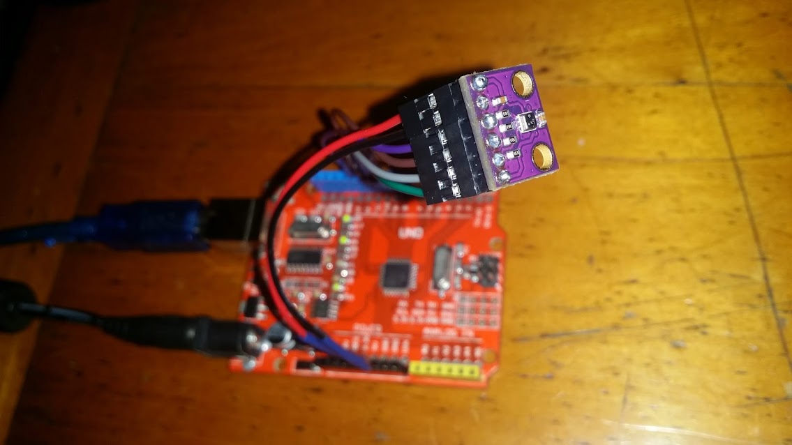
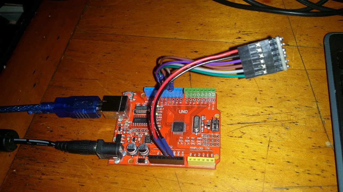
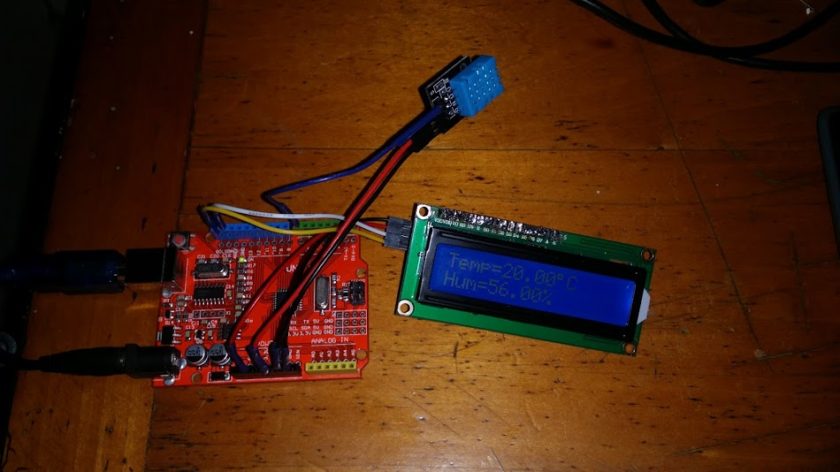
Now a couple of pictures of the test set.


DEMASIADO UTIIIIIIIL, MUCHISIMAS GRACIAS
Hay una confusión. En la conexión de fritzing usasta la adafruit bmp280 breakout board. Esa placa tiene un level shifting de 5v a 3,3, por lo que si se puede conectar directamente al arduino. En la conexión a tu arduino roja estás usando la GY-BME280-3.3 que, no posee el adaptador de 5 a 3,3 por lo que, si le conectas los 5v del arduino como alimentación lo dañarías.
Juan Carlos Suárez Barón. Sí, es correcto lo que dices. En realidad mi módulo soporta 5v y no es ese que indico allí (solo que es muy parecido). Voy a corregir el artículo. Muchísimas gracias por la corrección.
De nada.
Estoy tratando de usar el GY-BME280-3.3 conectado al Feather Huzzah pero me ha dado error al crear el objeto bmp.
Tendrás algun ejemplo con Huzzah o alguna idea de por que no me funcione ?
SE supone que lo estoy usando como I2C asi que solo conecto Vcc, Gnd, y las dos señales.
No he experimentado con ese componente. El código GY-BME280-3.3 me hace suponer que es de 3.3 voltios. ¿Es lo que te entrega y con lo que funciona el Huzzah? Estás usando el IDE de arduino o LUA?
[…] El sensor BME280 utilitza diferents llibreries en funció del projecte que es disseny i del protocol (I2C o SPI) que es vulgui utilitzar. El projecte que proposo usa el protocol I2C i està basat en un exemple de Lambort de Seeedstudio. La llibreria del sensor (Grove_BME280-master.zip) se ha de baixar de Github. Es clica en Clone or download i es baixa el ZIP. Si en lloc del protocol I2C es vol utilitzar el SPI, es pot consultar la pàgina de Enrique Latorres. […]
como le agrego display lcd ???
Hay otro post con un display LCD. https://enrique.latorres.org/es_ES/2017/10/20/arduino-i2c-lcd-display-project-with-malpartida-library/
Hay otro post sobre usar LCD de dos o cuatro líneas https://enrique.latorres.org/es_ES/2017/10/20/arduino-i2c-lcd-display-project-with-malpartida-library/