


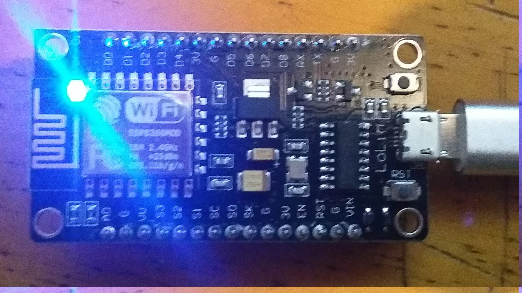
Estoy probando el Lolin NodeMCU V3 esp8266. Este es un pequeño microcontrolador con wifi incorporado. El modelo que estamos probando tiene 1 MB de flash ram más 8k de RAM dinámica. Estos es más que suficiente para muchos propósitos.
Estoy usando Arduino IDE sólo por simplicidad ya que es lo que usé para otros ejemplos. Pero NodeMCU tiene un framework Lua, esto es que se puede subir scripts de Lua al NodeMCU, vincularlos al script init.lua y ejecutarlo. No voy a mostrar el ejemplo de Lua en este post, sino el ejemplo de IDE de Arduino.
El IDE de Arduino se puede personalizar para varios controladores que no son equivalentes o compatibles con el Framework Arduino. Para esto se debe incluir un crosscompiler, algunos scripts y definiciones tienen que ser construidos. Y hay una manera de decir a Arduino IDE que incluya a estos en el IDE.
Para que su Arduino IDE sepa cómo trabajar con Lolin NodeMCU tenemos que incluir el plugin.
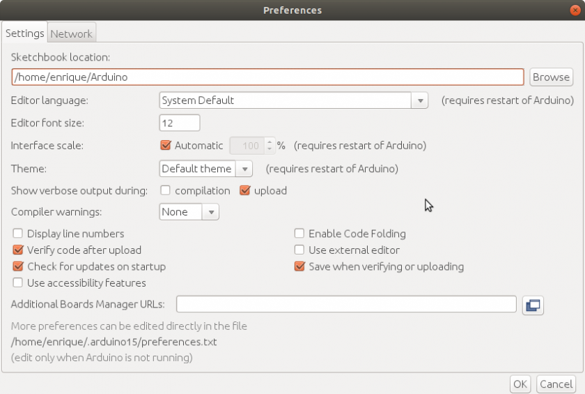
Inicie su IDE de Arduino y seleccione File|Preferences. Se abre un formulario y en el TextBox «Additional Boards Manager URLs:» escribimos «http://arduino.esp8266.com/stable/package_esp8266com_index.json« y hacemos click en [OK].
Ahora tenemos que descargar el plugin y las bibliotecas.
Así que hacemos clic en Tools|Board|NodeMCU 1.0 (ESP-12E Module). Esto selecciona nuestro nuevo tablero para trabajar.
Ahora hacemos click en Tools|Board|Board Manager… y buscamos la tarjeta esp8266. La seleccionamos y hacemos click en Install]. Se tarda un tiempo, pero esto instala el plugin y los módulos necesarios.
Ahora podemos enchufar el NodeMCU con un cable micro usb a nuestra computadora. Debiera reconocer un dispositivo de comunicaciones serial. En mi caso se conecta en /dev/ttyUSB0. Tu puedes verificar en tu sistema Linux con el comando: dmesg | grep tty
Asegúrese que está seleccionado Tools|Board|NodeMCU 1.0 (ESP-12E Module). También seleccione Upload Speed a 115200. Y asegúrese que el usuario de la computadora está en el grupo dialup. Para los usuarios de Windows, pueden encontrar indicaciones para esto en cualquier otro lugar de Internet.
Ahora estamos listos para hacer nuestro primer programa.
Vamos a hacer un Servidor Web que enciende o apaga el LED azul de la placa.
Este programa fue modificado del que aparece en Quick-Start-to-Nodemcu-ESP8266-on-Arduino-IDE
Ese ejemplo no usa el LED azul incorporado. Además el LED azul está invertido. Esto es que el nivel bajo del pin lo enciende, mientras que el nivel alto lo apaga.
Tu deberás insertar el nombre de tu red wifi y la clave en las variables ssid y password variables. Esto es necesario para que el NodeMCU se conecte a tu red inalámbrica.
#include
const char* ssid = "your_wifi_name";
const char* password = "your_wifi_password";
int ledPin = 2; // Arduino standard is GPIO13 but lolin nodeMCU is 2 http://www.esp8266.com/viewtopic.php?f=26&t=13410#p61332
WiFiServer server(80);
void setup() {
 Serial.begin(115200);
 delay(10);
pinMode(ledPin, OUTPUT);
digitalWrite(ledPin, HIGH);
// Connect to WiFi network
Serial.println();
Serial.println();
 Serial.print("Connecting to ");
 Serial.println(ssid);

WiFi.begin(ssid, password);

while (WiFi.status() != WL_CONNECTED) {
 delay(500);
 Serial.print(".");
 }
 Serial.println("");
 Serial.println("WiFi connected");

// Start the server
 server.begin();
 Serial.println("Server started");

// Print the IP address
 Serial.print("Use this URL to connect: ");
 Serial.print("http://");
 Serial.print(WiFi.localIP());
 Serial.println("/");

}

void loop() {
 // Check if a client has connected
 WiFiClient client = server.available();
 if (!client) {
 return;
 }

// Wait until the client sends some data
 Serial.println("new client");
 while(!client.available()){
 delay(1);
 }

// Read the first line of the request
 String request = client.readStringUntil('r');
 Serial.println(request);
 client.flush();

// Match the request
 //Lolin nodeMCU has inverted the LED.
 //Low level turns on the led
 //while High level turns it off

int value = HIGH; //initially off
 if (request.indexOf("/LED=OFF") != -1) {
 digitalWrite(ledPin, HIGH);
 value = HIGH;
 }
 if (request.indexOf("/LED=ON") != -1) {
 digitalWrite(ledPin, LOW);
 value = LOW;
 }

// Set ledPin according to the request
 //digitalWrite(ledPin, value);

// Return the response
 client.println("HTTP/1.1 200 OK");
 client.println("Content-Type: text/html");
 client.println("");
 client.println("<!DOCTYPE HTML>");
 client.println("<html>");

client.print("Led pin is now: ");
 //High=off
 //Low=on

if(value == HIGH) {
 client.print("Off");
 } else {
 client.print("On");
 }
 client.println("");
 client.println("<a href=\"/LED=ON\"\"><button>Turn On </button></a>");
 client.println("<a href=\"/LED=OFF\"\"><button>Turn Off </button></a><br />");
 client.println("</html>");

delay(1);
 Serial.println("Client disonnected");
 Serial.println("");
}
Compile y cargue el programa en su NodeMCU. Va a mostrar una secuencia de puntos y un porcentaje hasta que llegue a [100%]. Entonces el programa estará cargado y corriendo. Active el Tools|Serial Monitor. Asegúrese que está configurado a 115200 baudios. Va a responder algo como esto:
load 0x4010f000, len 1384, room 16
 tail 8
 chksum 0x2d
 csum 0x2d
 v09f0c112
 ~ld

Connecting to your_wifi_name
 ..
 WiFi connected
 Server started
 Use this URL to connect: http://192.168.1.102/
La dirección 192.168.1.102 (Puede ser diferente en su sistema) es la dirección en la que el Servidor Web está escuchando las solicitudes.
Cuando se conecta a esta dirección, en el navegador se obtiene lo siguiente:
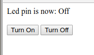
El LED inicialmente está apagado. En el Serial Monitor usted puede ver que el navegador se ha conectado al servidor.
new client
 GET / HTTP/1.1
 Client disonnected

new client
 GET /favicon.ico HTTP/1.1
 Client disonnected
Puede ser levemente diferente en su sistema. Cuando se hace click en el botón de [Turn On] se enciende el LED en la tarjeta y el Monitor Serial lee:
new client
 GET /LED=ON HTTP/1.1
 Client disonnected

new client
 GET /favicon.ico HTTP/1.1
 Client disonnected
Cuando se hace click en el botón [Turn Off] en el navegador se obtiene un LED apagado y la sigueinte respuesta en el Monitor Serial:
new client
GET /LED=OFF HTTP/1.1
Client disonnected

new client
GET /favicon.ico HTTP/1.1
Client disonnected
Ahora usted tiene un LED controlado mediante http.
The only gripe I have of the V3, is the width. It occupies the entire height of a breadboard from the outer 5-pin sockets.. One hack someone suggested, getting a short Minimum 15-pin width (5X15) breadboard, and sawing it right down the center, so the 5-point rails could be placed further apart. (have done so already with an old Radioshack breadboard. 276-0003, and cut it right down the center of the chip area.)
I’m still trying to figure out LUA on both the -01 & the -12 on the Lolin.. (had been running stock NodeMCU, recently updated to a custom from https://nodemcu-build.com/ (does the build from the V2.1.0 source, allowing you to pick which modules to add, then EMAILS You the Float & Integer firmwares.)
Similar in ESPBasic http://www.esp8266.com/viewtopic.php?f=40&t=4850
Yes. It is similar to several others. Another is cited in the post. But this one you pointed to i sa little more interesting because gets more information on its web site like number of blinks, delay and pin to use… That one is already a modification from another…. https://www.esp8266basic.com/blink-example.html
Thanks…
Sawing the breadboard is a clever idea, but will make it difficult for some other chips. In my case, I’ll adapt them for some geophysical data loggers, so most likely I’ll make a PCB with the adequate connectors in it.
I did not have time to experiment with LUA yet. But I will.
I had not tried custom builds from https://nodemcu-build.com/ but I will investigate about it…
Stephen, Thank you very much for your comments and information.
Hola,
Sabes como configurarlo para que acepte comandos AT, yo lo he flasheado con varios programas y versiones pero nada.
Saludos
En cuanto tenga un poco de tiempo voy a probar. ¿Qué es lo que quieres que haga con los comandos AT?
Algunos para probar.
https://www.instructables.com/id/Get-Your-ESP8266-12-Ready-for-AT-Commands/
https://www.instructables.com/id/Get-Started-With-ESP8266-Using-AT-Commands-Via-Ard/
Why is my serial monitor printing: HpY>$(⸮⸮D:h⸮⸮⸮B⸮⸮⸮E⸮P⸮⸮
⸮⸮̋T-⸮⸮⸮⸮⸮⸮⸮⸮⸮⸮⸮⸮⸮⸮⸮⸮⸮⸮⸮⸮⸮⸮⸮⸮⸮⸮⸮⸮⸮⸮⸮⸮⸮⸮⸮⸮⸮⸮⸮⸮⸮⸮⸮⸮⸮⸮⸮⸮⸮⸮⸮⸮⸮⸮⸮⸮⸮⸮⸮⸮⸮⸮⸮⸮⸮⸮⸮⸮⸮⸮⸮⸮⸮⸮⸮
Most likely your serial communications speed/baudrate is not set properly. Make sure they both coincide to 115200 that is set on the IoThing or change the program to fit your serial monitor speed. See.. «… Serial.begin(115200); …»
no me contecta a serial, solo aparece una red wifi farylink y no me aparede algo mas
Tenés que explicar mejor cual es el entorno con el que estás trabajando. Verificá la velocidad de transmisión serial.
Try to change monitor from 57600 baud to 115200 baud